Author: Huang Publish Time: 23-03-2026 Origin: Site


If you’re choosing solar street lights for real-world projects—roads, campuses, parking lots, or courtyards—the control strategy matters as much as the wattage. The right control modes balance safety, autonomy days, and lifetime cost; the wrong ones drain batteries, shorten lifespans, and trigger complaints. This guide explains the core control systems and maps them to common scenarios with defensible parameter ranges you can use as a starting point. Throughout, we call out standards context (IES RP-8, EN 13201) and practical sizing logic.
Most solar lighting specifications still fixate on “watts” and “lumens,” yet field performance hinges on how the system behaves across the night and across seasons. That’s what control modes determine—when to turn on, how bright to run, when to dim or boost, and how to react to motion or remote commands. In the sections below, we’ll define the building blocks, summarize the major solar street light control modes, and show how to pick a mode package per scenario with PV, battery, and optics that realistically meet your targets.
Before pairing applications to modes, lock in the fundamentals: how controllers harvest energy, how batteries are protected, and how standards frame “good lighting.”
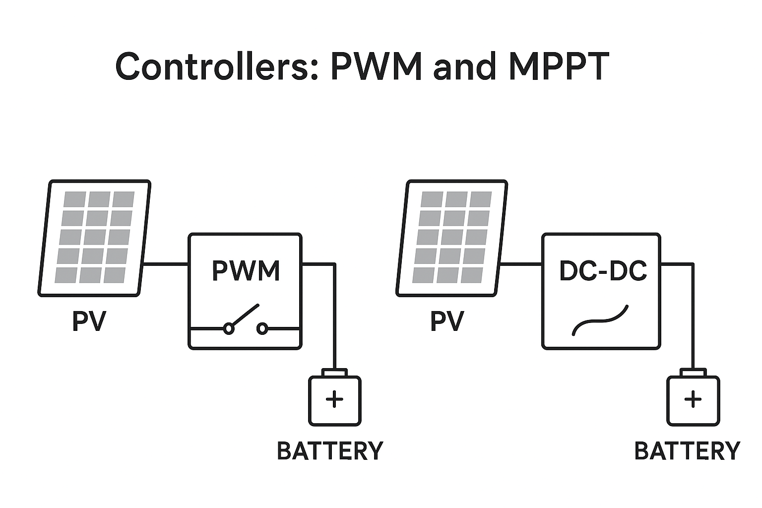
Pulse-width modulation (PWM) controllers tie the PV array closely to battery voltage and regulate by pulsing. They’re simple and cost-effective but leave energy on the table when panel voltage is well above battery voltage or when irradiance is variable. Maximum power point tracking (MPPT) controllers continuously track the PV array’s maximum power point via DC–DC conversion to harvest more energy, especially in cold weather and low-irradiance conditions. Morningstar notes that MPPT can increase harvest by about 5–30% compared to PWM, depending on conditions. See the explanation in the manufacturer’s overview: the gains are summarized in the Morningstar FAQ on controller types. Victron’s documentation also references up to roughly 30% more harvested energy versus PWM and highlights faster tracking benefits over slower MPPT algorithms, as described in the Victron MPPT features guide.
When does MPPT matter most? Think high-latitude winters, shaded or partially cloudy days, mismatched array-to-battery voltages, or projects where you need a smaller panel for the same autonomy. In benign, sun-rich climates with modest loads, PWM can still be an acceptable choice if you size with margin.
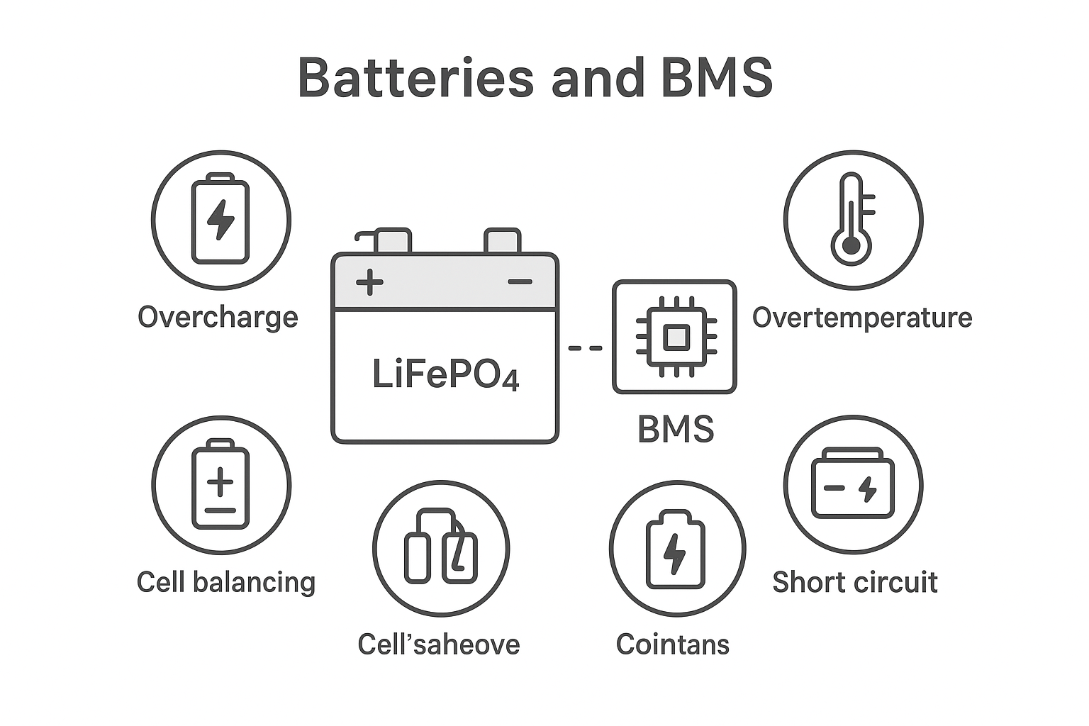
For modern solar street lights, LiFePO4 (LFP) batteries are common due to long cycle life and stable thermal behavior. A battery management system (BMS) safeguards the pack with overcharge/overdischarge, overcurrent/short-circuit, and temperature protections, plus cell balancing and fault logging. These features are configurable in contemporary BMS chipsets; see representative capabilities in Texas Instruments’ documentation and Monolithic Power Systems’ LFP-focused devices. While street-light-scale packs are smaller than full energy-storage systems, the underlying safety philosophies align with industrial standards such as IEC 62619 and UL 1973.
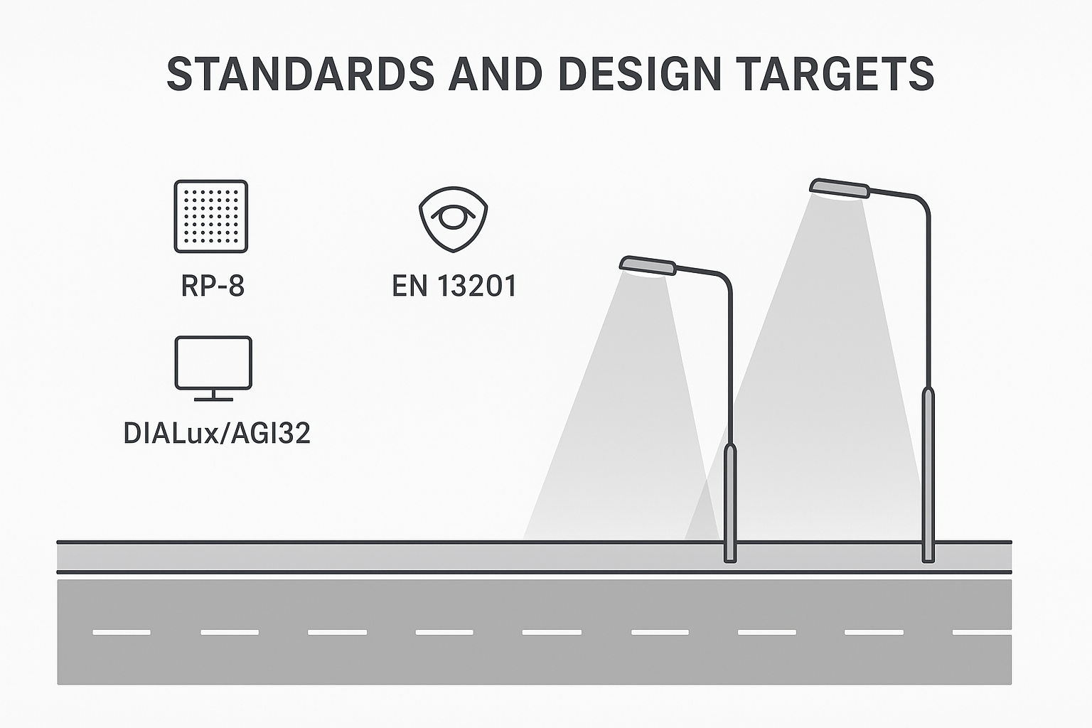
Public lighting should be verified against recognized practices rather than ad‑hoc illuminance guesses. Two widely used references are IES RP‑8 and EN 13201. RP‑8 in North America sets recommended practices for roadway and parking facility lighting, including design methods, uniformity, and glare control. For a high-level orientation, review the IES overview of the updated RP‑8 roadway standard. In Europe and many regions, EN 13201 defines lighting classes (M, C, P) with performance metrics and calculation/verification methods; see a series summary via a standards catalog overview of EN 13201 components for the photometric data workflow.
What does this mean for you? Use the chosen luminaire’s IES/LDT file in DIALux or AGi32, target the applicable class (e.g., local road vs. pedestrian path), check average levels and uniformity, and confirm BUG/glare. Then select control modes and energy storage to maintain those targets across seasons. Don’t rely on wattage alone.
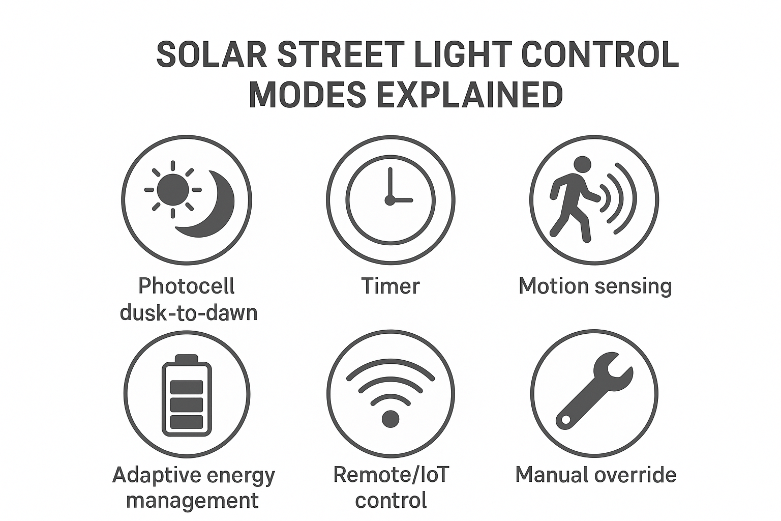
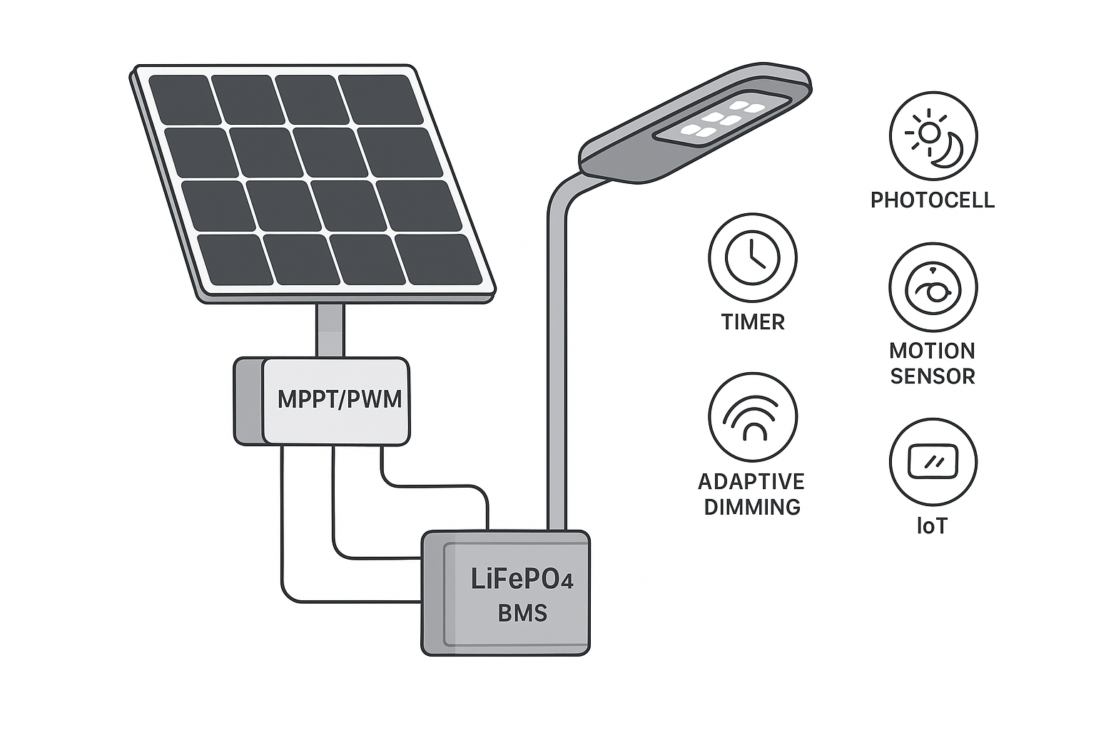
The phrase solar street light control modes covers how your lighting behaves hour by hour. Below are the common options and how they impact autonomy and safety.
The controller treats the PV panel (or a dedicated sensor) like a photocell. When ambient light drops, the lamp turns on; when dawn comes, it turns off. This is the simplest baseline and suits locations that require all-night lighting with no schedule changes.
Timer profiles split the night into blocks—for example, 100% output for the first 3–5 hours to handle peak activity, then 50–70% until dawn. Profiles can be seasonal. Practical programming behavior and common profiles are described in vendor field guides such as SEPCO’s discussion of operational profiles in the SEPCO article on keeping solar lights on all night.
Motion-based dimming keeps a low baseline (e.g., 10–30%) and boosts to 100% when motion is detected. Passive infrared (PIR) detects heat motion; it’s low power and generally resists outdoor false triggers when aimed correctly. Microwave (radar) has wider coverage and can “see” through some non‑metallic materials, but it draws more standby power and may false-trigger in windy or rainy conditions. Dual‑tech (PIR+microwave) can mitigate false alarms in high-security sites—just remember to include sensor standby power in the daily energy budget.
Adaptive or “energy‑aware” profiles monitor battery state of charge and shorten or dim parts of the night during poor weather to preserve autonomy days. This mode is valuable in monsoon seasons or high latitudes, trading brightness for guaranteed runtime.
Bluetooth, Zigbee, cellular, or LoRaWAN add remote diagnostics, firmware updates, profile changes, and alarms. These capabilities are best for fleets and remote assets; be sure to budget the telemetry standby Wh explicitly. For background on wireless lighting controls concepts, see the internal primer on connected dimming in the Zigbee lighting dimming beginner’s guide.
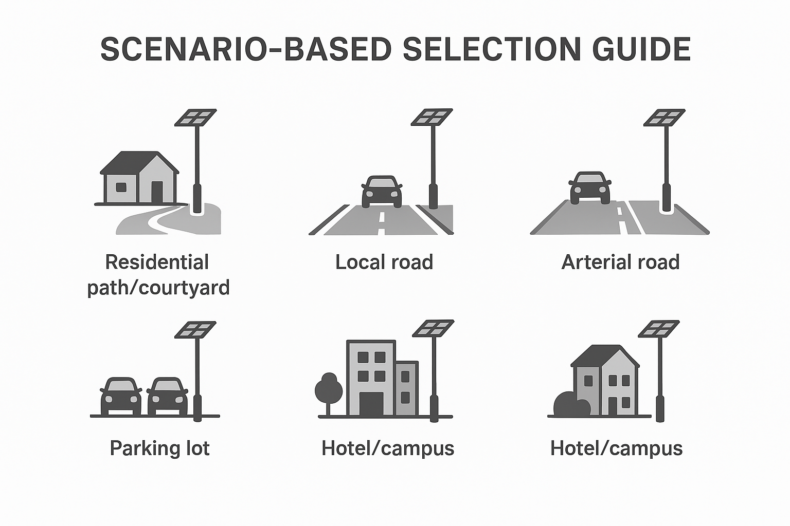
Here’s the decision-making core: matching applications to solar street light control modes and to sensible configuration ranges. Treat the table as a starting point; always validate with photometric software and local worst‑month solar data.
Vendors such as KEOU Lighting offer street and area-light packages that support dusk‑to‑dawn, timer blocks, motion‑boost dimming, and remote supervision. Use mode packages to hit safety targets without oversizing panels and batteries.
| Scenario | Recommended CCT |
Residential/courtyard paths | 2700–4000 K (warmer feels more comfortable near homes) |
Local roads (village/secondary) | 3000–4000K |
Collector/arterial segments | 3000–4000K |
Parking lots (open) | 3000–4000K |
Hotel/campus mixed use | 2700–3500 K near residences; 3000–4000 K on primary walkways |
Aim for comfortable, low‑glare lighting. Warmer CCTs (2700–3500 K) near doorways and seating feel welcoming. A 10–30% baseline with PIR boost preserves autonomy while keeping wayfinding light on. Keep poles 4–6 m where feasible to improve uniformity and reduce glare.
For local roads, pair Type II/III optics with 6–9 m poles and a dusk‑to‑dawn schedule that dims late at night. Validate uniformity in DIALux/AGi32 before finalizing wattage. MPPT is a practical default to ride out seasonal lows without oversizing panels.
Higher speeds and volumes demand stricter luminance targets per RP‑8/EN 13201. Here, energy‑aware adaptive profiles plus MPPT give you headroom during poor weather. Consider remote monitoring where maintenance access is limited.
Open lots benefit from Type V optics. Motion‑boosted profiles curb idle consumption while keeping perceived safety. In windy, rainy, or high‑traffic edges where false triggers are likely, dual‑tech sensors can help, but explicitly include their standby draw in your Wh budget. For examples of area lighting hardware used in perimeter/lot contexts, browse the Solar Flood Light category.
Mix comfort and safety: warmer tones near residences, neutral white on primary walkways, and vertical illuminance at entries. Photocell + timer works well; add PIR where late‑night activity is sporadic. IoT pays off for multi‑site campuses that tweak profiles seasonally.
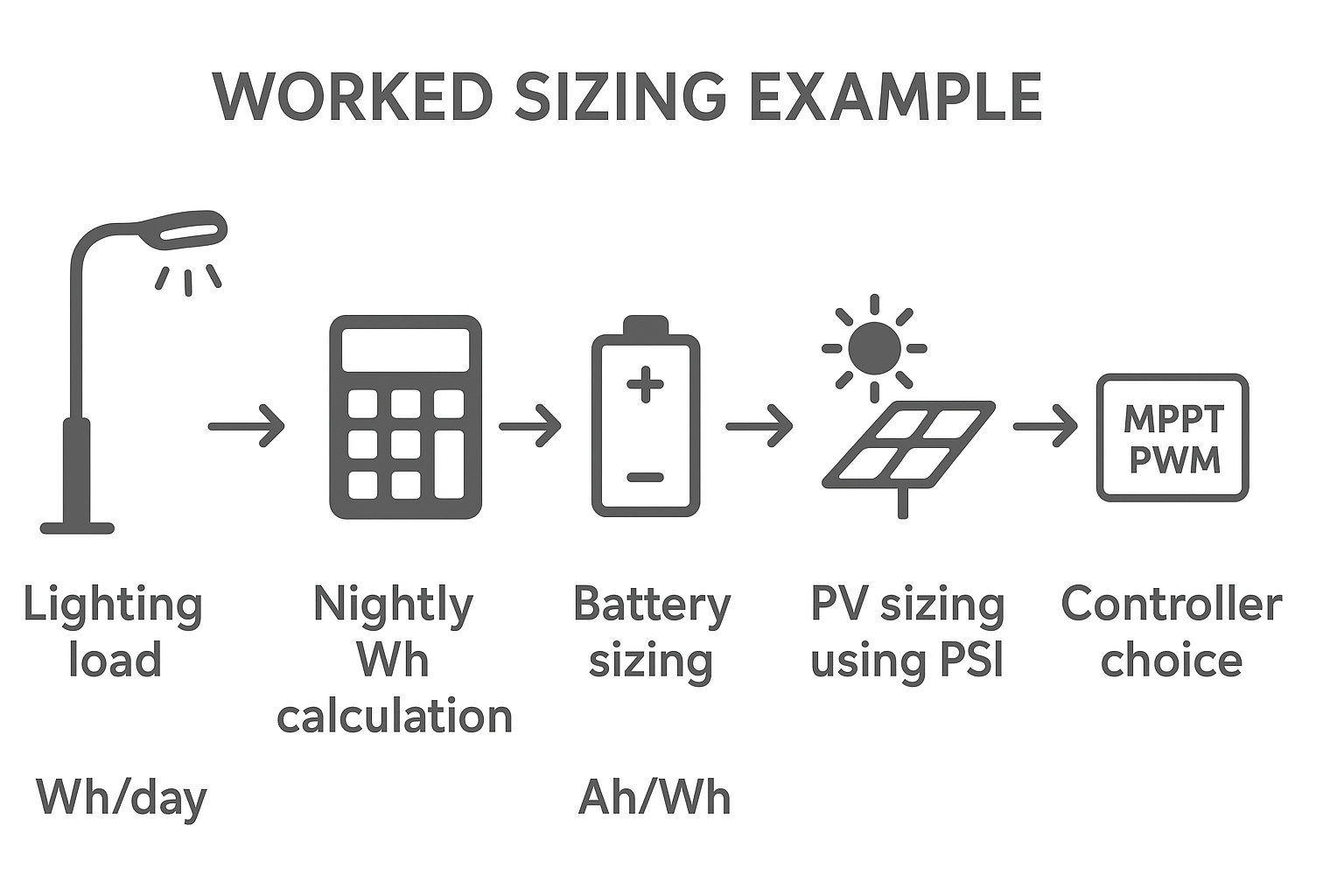
Think of sizing as balancing a nightly energy “budget” with a worst‑month “income.” Here’s a compact walkthrough for a local road luminaire.
Target: Local road, 8 m pole, Type III optics, time‑block schedule (100% for first 5 h; 60% for next 7 h). Fixture: 60 W LED at the driver input (assume driver/controller/wiring overall 85% round‑trip efficiency). Sensor/telemetry: PIR only, negligible standby.
Nightly energy need (DC to the battery): 60 W × (5 h × 1.0 + 7 h × 0.6) = 60 × (5 + 4.2) = 60 × 9.2 = 552 Wh. Divide by 0.85 system efficiency ≈ 650 Wh/day from the battery.
Autonomy: 3 days minimum → 1,950 Wh stored. Using LiFePO4 at 85% usable DoD → required nominal capacity ≈ 1,950 / 0.85 ≈ 2,294 Wh. For a 12.8 V LFP pack, that’s ≈ 179 Ah; round up to a 12.8 V, 200 Ah pack.
PV sizing: Use worst‑month peak sun hours (PSH). Suppose NREL NSRDB shows 3.0 PSH in the worst month for the site. Include 25% derate for temperature/soiling/tilt. Effective PSH ≈ 3.0 × 0.75 = 2.25. Required array power with MPPT: 650 Wh/day ÷ 2.25 h ≈ 289 W; add 20% margin → ~350 W. With PWM (lower harvest), assume MPPT’s 15% advantage would require ~350 × 1.15 ≈ 400 W to keep the same margin.
Where to pull PSH data? The NREL NSRDB dataset portal provides authoritative irradiance data; use the monthly minimum as your design anchor, then verify on‑site.
What’s the takeaway? The control profile (time blocks) kept Wh/day in check, while MPPT trimmed panel size to ~350 W versus ~400 W with PWM for similar margin. If you add IoT radios or a microwave sensor, re‑compute with their standby power.
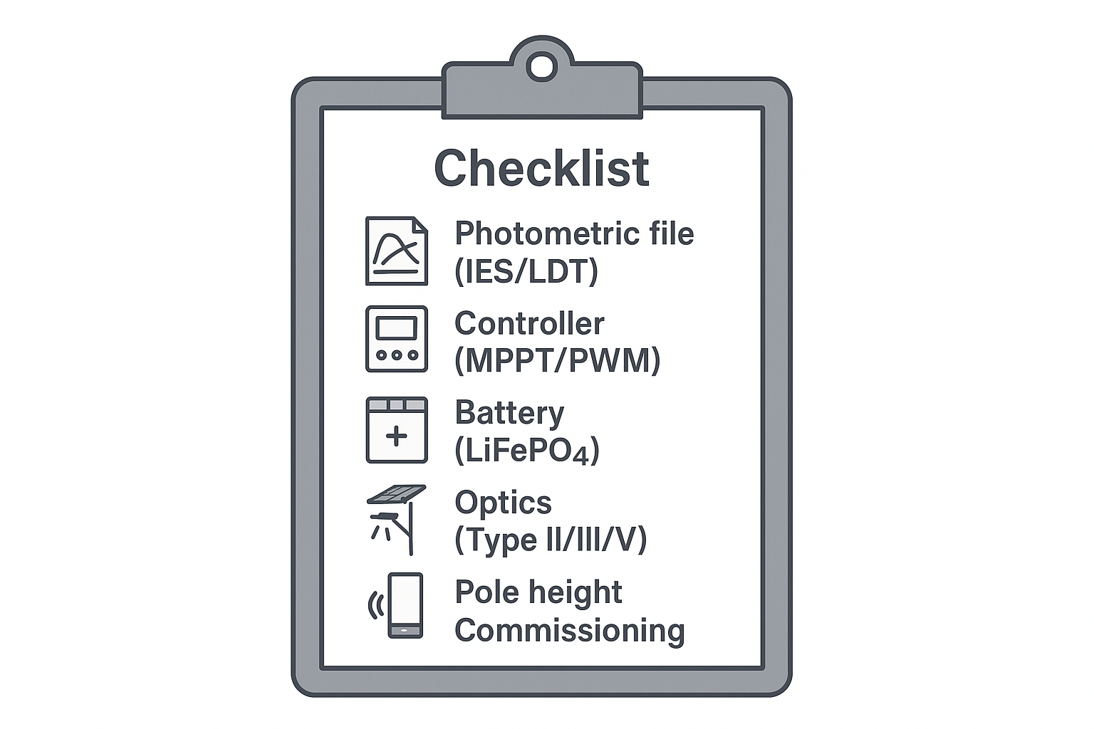
Use this short checklist to keep submittals tight and field performance predictable.
Confirm standards path: Which class in RP‑8/EN 13201? Provide DIALux/AGi32 files with average levels, uniformity, and BUG.
Declare the mode package: photocell only; photocell + timer blocks; baseline dim + PIR; adaptive; remote/IoT. Include baseline percent, boost percent, and block times.
Specify controller type and setpoints: MPPT or PWM; battery LVP/HVP; temperature cutbacks; motion sensor type and standby draw.
Size with worst‑month PSH: State source, assumptions, and margins; list panel W, battery Wh, autonomy days, and chemistry.
Include optics and poles: Distribution type, mounting height, spacing target, bracket tilt if used.
Firmware and commissioning: Default profile on delivery, field‑override method (IR, Bluetooth, gateway), and logging.
Most “it doesn’t last the night” calls trace back to either mode misalignment (too much full‑power time) or seasonal PSH assumptions that were too optimistic. Start with a simple triage: Is the baseline dim value too high? Did the winter profile load get updated? Has soiling or shading increased? Next, check BMS fault logs and temperature cutbacks. Motion false‑triggers? Re‑aim PIR sensors to avoid hot exhaust paths and waving foliage; reduce microwave sensitivity or switch to dual‑tech if the site demands it. Finally, pilot a small sample of poles with the intended profiles before a large roll‑out—two weeks across bad weather will tell you more than any spreadsheet.

MPPT vs PWM fundamentals and expected gains are summarized in the Morningstar controller types FAQ and in the Victron MPPT features documentation.
For roadway and parking facility design concepts, see the IES overview of the updated RP‑8 standard.
European class selection and photometric verification workflows are discussed across the EN 13201 series summaries in standards catalogs.
Practical mode behaviors and profiles appear in vendor field notes such as the SEPCO guide to keeping solar lights on all night.
For site‑specific insolation, consult the NREL NSRDB data portal.
—
Looking to understand broader outdoor lighting options beyond street and path applications? Browse the Outdoor Lighting Solution overview for portfolio context and integration ideas.


