Author: Huang Publish Time: 24-03-2026 Origin: Site


Municipal teams are often choosing between integrated (all‑in‑one) and split‑type solar street lights. The right pick depends less on brand and more on deployment speed, O&M capacity, climate, power needs, and roadway class. Here’s the short version: if you need rapid rollouts with limited maintenance resources, integrated usually wins; if you need long autonomy or higher power on main corridors, split‑type is the safer bet.

This article compares split‑type vs integrated solar street lights for municipal programs, with a focus on installation simplicity, modular replacement, and matching the luminaire to different road designs. The lens is procurement and engineering: minimize traffic disruption, meet EN 13201 or IES RP‑8 class targets, and keep operations predictable.
Procurement and tender leads who need an architecture decision for upcoming bids
Lighting designers, consultants, and road engineers validating feasibility before simulation
O&M managers optimizing truck rolls, spare parts, and MTTR across a growing solar fleet

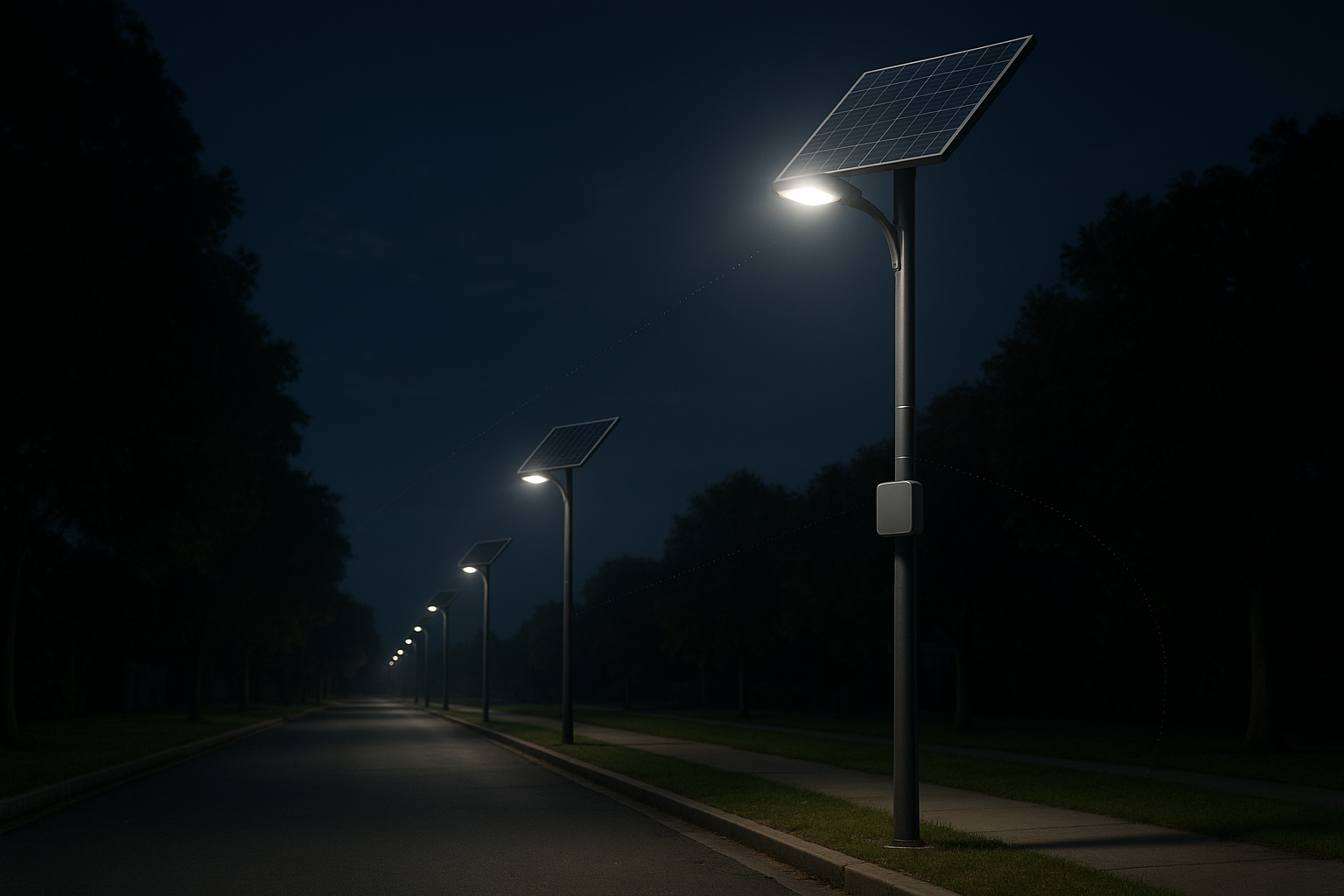
Integrated (all‑in‑one) combines panel, LiFePO4 battery, controller, and LED engine in one compact head. Split‑type separates the panel (and often the battery/controller) from the luminaire, enabling bigger arrays, adjustable tilt, and thermal separation.
Integrated units streamline installation and reduce connection points, which lowers ingress and wiring risks. They present a neat profile with smaller sail area and are visually consistent across corridors. Constraints include limited room for larger PV and batteries, often fixed or limited panel tilt, and thermal coupling inside the head that may shorten battery life in very hot climates.
Split‑type systems scale energy easily: larger, optimally tilted panels and higher‑capacity batteries extend autonomy for higher latitudes and long rainy spells. Thermal separation helps battery longevity, and higher‑power roadway classes are easier to support. Downsides are longer installation time, more QA points and connectors, larger sail area that drives pole/bracket engineering, and a busier streetscape if not carefully detailed.
Below is a municipal‑oriented view using current mainstream components (LiFePO4, MPPT, monocrystalline ~20–23% eff., LED 150–190 lm/W). Values are representative and model‑dependent as of 2026‑03‑24 and based on typical vendor method statements and public datasheets, not on a single standardized timing study.
| Dimension | Integrated (All‑in‑One) | Split‑Type (Separate Panel and Battery) |
Installation time per pole | Fastest. After the pole is ready, typical mounting and commissioning can be minutes; fewer parts and little to no wiring. Industry guides commonly show streamlined steps. | Longer. Mount head, mount tilted panel, mount battery box, route and connect cables, verify polarity, test. Expect more minutes and crew coordination than integrated per standard method statements. |
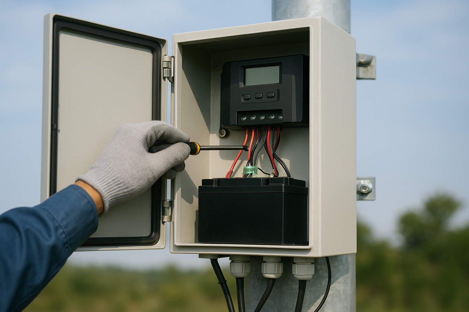
Modular serviceability and MTTR | Often whole‑head swap is straightforward; internal component swaps depend on enclosure design. Fewer exposed connectors reduce ingress/polarity risks. | Battery and controller are usually accessible in a box; LED driver swaps are simple; component‑level MTTR is typically favorable with clear spare SKUs. |
Energy scalability (panel/battery) | Limited by compact head volume and panel area; tilt may be constrained. | Strong. Larger PV and higher Wh/Ah batteries; tilt angle optimized for latitude/season. |
Autonomy in harsh climates | Adequate in moderate climates using dimming profiles; constrained for ≥4–5 night targets. | Better suited to ≥4–5 night targets in rainy/high‑latitude contexts with adjustable tilt and bigger storage. |
Optical performance vs road class | Architecture‑neutral. Achieves targets with the right lens, wattage, and spacing. | Same: model‑dependent. Benefit is easier scaling to higher wattages for main roads. |
Smart control readiness | Common support for multi‑period dimming and motion‑boost; remote telemetry available on select packages. | Same. Controllers often support timers, motion, and remote telemetry via add‑on modules. |
Wind load and mechanics | Lower sail area; simpler bracketry. Good for design‑sensitive corridors. | Higher sail area; pole/bracket must be engineered to local wind maps; consider vertical or dual‑panel layouts where needed. |
Thermal and battery life | Battery‑in‑head can run hotter in warm regions, which may reduce cycle life. | Thermal separation and shading options favor battery longevity; heaters can be accommodated in cold zones. |
Procurement and deployment risk | Simpler BOM, fewer QA points, quicker training. Less flexible for late autonomy up‑sizes. | More QA points and spares; better fit for evolving autonomy or power requirements over program life. |
For roadway lighting practice, refer to concise explainers on class selection and adaptive dimming floors in IES and EN standards, such as the U.S. guidance summarized in the Federal Highway Administration Lighting Handbook (2023) and municipal references that align to RP‑8 updates. See the overview context in the FHWA’s Lighting Handbook and NYC DOT’s photometric standards referencing RP‑8‑22: FHWA Lighting Handbook, 2023 and NYC DOT photometric standards referencing RP‑8‑22, 2025. For controller feature exemplars, a single product‑class reference is sufficient: see Phocos CIS‑N‑MPPT‑LED. For preliminary wind checks, one authoritative tool is adequate: the ASCE‑aligned pole wind load calculator.

Start from two anchors: 1) deployment realities (crew skill, lane closures, commissioning time), and 2) site energy needs (latitude, rainy seasons, target autonomy nights). Think of it this way: installation and O&M drive your first pass; then optical and wind mechanics finalize pole heights and spacings in DIALux or AGi32.
If you must light local or collector roads quickly with limited O&M staffing, integrated typically shines. Fewer parts mean fewer mistakes and fewer ingress points. Commissioning is simpler, so you can standardize method statements and train crews faster. For temporary works or fast‑track corridors that later migrate to grid or hybrid, integrated heads are easy to redeploy.
If winter insolation is low, or you regularly see multi‑day cloudy spells, split‑type architecture is more resilient. Scalable PV and batteries, plus adjustable tilt, help you hit 4–5 night autonomy targets without oversizing the luminaire. In cold regions, battery boxes allow heaters and controlled charging, reducing lithium plating risk and protecting cycle life, consistent with LiFePO4 operating range guidance summarized by battery manufacturers.
For arterials and highways where pole heights and spacings push lumen packages higher, split‑type solutions are easier to configure. Larger arrays and storage buffer dimming profiles so you can respect adaptive lighting floors in practice while still meeting maintained illuminance or luminance requirements set by IES RP‑8 or EN 13201 classes.
Where the visual profile matters—historic districts or flagship boulevards—integrated heads keep the look consistent and minimize sail area. That can reduce pole sizing and bracket complexity while keeping the daytime streetscape clean.
A little preparation goes a long way. Below are compact, field‑tested steps you can adapt into method statements and toolbox talks.
Verify pole foundation and conduit; pre‑check bolt circle and door access. Mount the head at the specified height and orientation, torque to spec, program controller profile, and perform a dusk simulation test.
Serviceability: Crews can often swap an entire head fast if faulted, minimizing MTTR. Component‑level swaps depend on the enclosure layout; fewer connectors reduce failure points.
Method highlights: Mount luminaire; mount panel with latitude‑appropriate tilt; route UV‑resistant cabling; install and seal battery/controller box; verify polarity; program profile; simulate dusk and motion‑boost. Risk controls: protect connectors from water ingress, strain‑relieve cables, and document torque on panel brackets. Expect a longer but predictable install with clear QA checklists.
For controller features and programming approaches (multi‑period timers, adaptive dimming, motion‑boost), see a practical explainer on mainstream solar control modes in this neutral resource: guide to solar street light control modes.
Both architectures can meet smart city needs with the right controller: multi‑period dimming, motion‑boost, and remote telemetry via modules (LoRaWAN, NB‑IoT, or 4G) are commonly available from mainstream controller vendors. Document compatibility with your municipal platform inside the specification and attach the intended dimming profiles to the tender.
On compliance, architecture does not decide conformity by itself. Compliance follows photometry and design: select distributions, set pole heights and spacings, and validate maintained levels and uniformity in DIALux/AGi32. Adaptive profiles should keep activity floors consistent with your adopted standard, as summarized in RP‑8 updates and municipal guidance.

Wind loads scale with effective projected area. Integrated heads generally present a smaller sail area, while split‑type panels add drag and require engineered brackets and poles matched to local wind maps. For preliminary sizing, many teams use ASCE‑aligned pole calculators before sealed calculations: ASCE‑aligned pole wind load calculator.
Bill of materials and QA points: integrated minimizes BOM complexity and training overhead; split‑type increases QA points but gives you knobs to turn later—panel/battery upsizing, heater kits, and controller upgrades. Spares strategy: integrated fleets often stock whole heads for rapid swaps; split fleets carry batteries, controllers, and panels to enable component‑level MTTR. Lead times and pole engineering need earlier lock‑in for split‑type programs due to bracket and pole class dependencies. To browse representative product families and outdoor solutions in a neutral way, see these hubs: street light product hub and outdoor lighting solution overview.
Here’s the deal: pick the winner per corridor, not in the abstract. If you prioritize rapid deployment with limited O&M crew capacity, choose integrated for local and collector roads. If your climate or road class demands higher power or ≥4–5 nights of autonomy, choose split‑type to scale PV, tilt, and storage. If the urban design team wants a clean profile with smaller sail area, choose integrated. If your smart city platform dictates specific telemetry, pick the architecture that supports your preferred controller and communications stack.
For readers exploring solution catalogs and control mode practices, these neutral references may help while you finalize architecture and specifications: the street light category overview for families and optics options, and the concise guide to solar street light control modes. These resources reflect mainstream practices and can inform specification drafts without steering brand selection.
Q1:Which option installs faster on average
Integrated usually installs faster because there are fewer components and connections. Crews mount the compact head, program the profile, and commission. Split‑type adds panel and battery box mounting and cabling, so plan extra minutes and QA steps.
Q2:How do I choose by road class without violating standards
Select distributions and lumen packages to meet your adopted standard (EN 13201 or IES RP‑8) and validate in DIALux/AGi32. The architecture choice affects energy and mechanics, not the photometric math. Keep adaptive dimming above the activity floors noted in RP‑8 updates.
Q3:What about high‑latitude or long rainy seasons
Favor split‑type. Larger PV, adjustable tilt, and higher‑capacity batteries help sustain multi‑night autonomy. In cold zones, battery boxes can host heaters for safer charging.
Q4:How does wind affect pole and bracket selection
Split‑type panels increase effective projected area and drag. Use local wind maps and ASCE‑aligned calculations to size poles and brackets, then obtain sealed calculations for tender packages.
Q5:Can both architectures support remote monitoring
Yes. With appropriate controllers and communications modules (e.g., LoRaWAN, NB‑IoT, or 4G), both can report status, faults, and support time‑dimming or motion‑boost. Verify compatibility with your municipal platform and document it in the spec.
References cited above (kept concise for link density control): FHWA Lighting Handbook, 2023; NYC DOT photometric standards referencing RP‑8‑22, 2025; Phocos CIS‑N‑MPPT‑LED; ASCE‑aligned pole wind load calculator.


