Author: Huang Publish Time: 12-02-2026 Origin: Site


 Procurement teams and distributors often need a single, practical reference that maps the bill of materials, what each part does, and which specs to verify before issuing a purchase order. This guide explains the LED panel light components with a selection lens: what changes between edge‑lit and backlit designs, how materials and the thermal path drive reliability, which driver and optics metrics matter, and how to confirm compliance with UL/IEC, DLC, and IES testing. It’s written for buyers who balance cost, delivery, warranty, and after‑sales support—and who need a clear checklist to reduce risk. We’ll keep the tone neutral and focus on verifiable criteria.
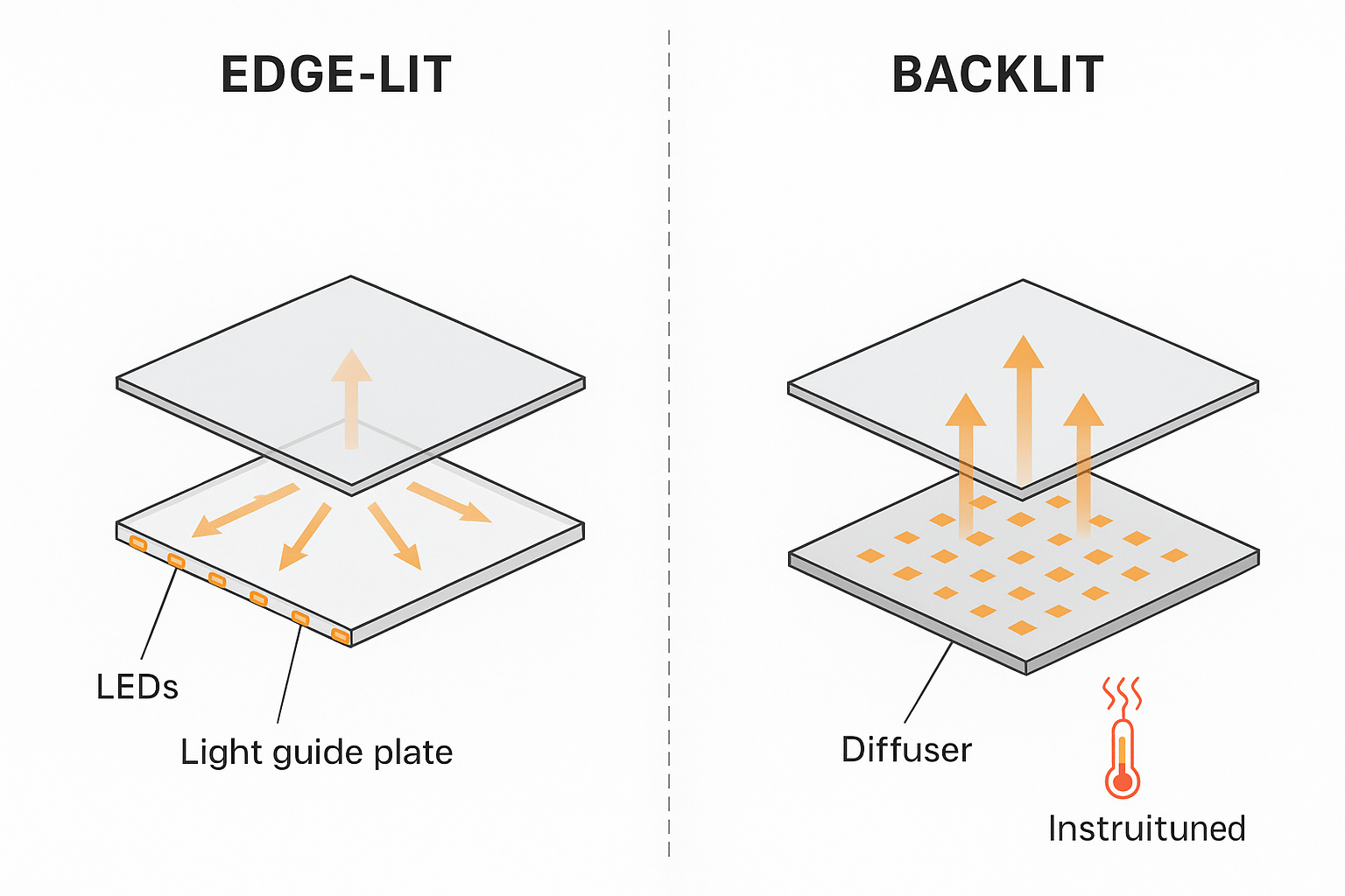
Edge‑lit and backlit panel lights share similar housings and drivers, but the internal optics and LED layout differ in ways that affect cost, thickness, uniformity, and thermal behavior—key considerations when shortlisting suppliers.
Edge‑lit: LEDs are arranged along the perimeter, injecting light sideways into a light guide plate (LGP)—usually PMMA or PC—with micro‑etched patterns that spread light across the face. A diffuser (often microprismatic) sits on top to smooth luminance and control glare. Thermal concentration happens near the edges, while the central area stays cooler.
Backlit: A direct LED array sits behind the diffuser, often on a metal‑core PCB (MCPCB). There’s no LGP, which simplifies the optical path and can improve efficacy. Thermal load is distributed across the panel surface but can create local hotspots if spacing and diffusion are inadequate.
Cost/BOM: Edge‑lit adds LGP complexity but may use fewer LEDs; backlit removes the LGP yet often needs more emitters and mechanical spacing. Your procurement decision should weigh BOM differences against uniformity and glare goals.
Efficacy: Backlit designs can achieve higher lm/W in many cases thanks to fewer optical interfaces; however, well‑engineered edge‑lit panels can be highly efficient.
Thickness and aesthetics: Edge‑lit enables slim profiles desirable for low‑clearance ceilings and modern interiors. Backlit typically requires more depth.
Thermal behavior: Backlit arrays spread heat across the face but demand robust heat‑spreading; edge‑lit localizes heat at the perimeter. In both cases, the thermal path—frame, MCPCB, thermal interface materials (TIMs), and enclosure—must conduct heat away efficiently.
| Attribute | Edge‑lit Panel | Backlit Panel |
LED layout | Perimeter LEDs + LGP | Direct LED array behind diffuser |
Thickness | Slim, low‑profile | Thicker, needs spacing |
Uniformity | High if LGP is precise | High if diffuser/spacing optimized |
Efficacy | Slightly lower (more optical interfaces) | Often higher (simpler optical path) |
BOM | LGP adds cost, fewer LEDs | More LEDs, simpler optics |
Thermal | Heat concentrated at edges | Heat spread across face; watch hotspots |
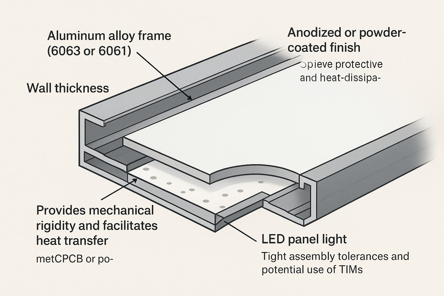
The frame isn’t just a cosmetic part. It handles mechanical rigidity, helps dissipate heat, and protects optical alignment. For procurement, materials and finishes are reliability‑critical.
Extruded aluminum frames are common. Suppliers often use 6063 for good surface finish and extrusion characteristics; 6061 offers higher strength but different finish behavior. Verify wall thickness and extrusion quality.
Finishes: Anodizing improves corrosion resistance and emissivity (helpful for radiative heat loss). Powder coating adds durability; confirm adhesion and thickness.
Rigidity prevents bowing that could misalign optics and create brightness artifacts. Ask for mechanical drawings and tolerances.
Thermal spreading: A continuous metal path from MCPCB to frame reduces junction temperatures. Specify tight assembly tolerances to maximize contact and add TIMs where interfaces break continuity.
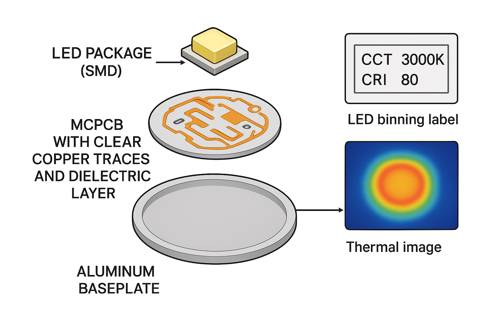
LED package selection and substrate design determine efficacy, color consistency, and thermal behavior. These are foundational LED panel light components for reliability and visual quality.
Packages: Mid‑power SMDs are common; some designs use COB arrays for compactness and high output. Request binning information (CCT/CRI tolerances) to ensure color stability across batches.
Drive currents: Moderate currents reduce thermal stress and prolong life; align with driver capabilities and flicker requirements.
MCPCB: Confirm copper thickness (e.g., 1 oz/2 oz), dielectric thermal conductivity, and baseplate (usually aluminum). A better stack‑up lowers thermal resistance.
Soldering: Even, void‑free joints ensure heat transfer and reliability. Consider incoming QA with thermal imaging or sample teardown reports.
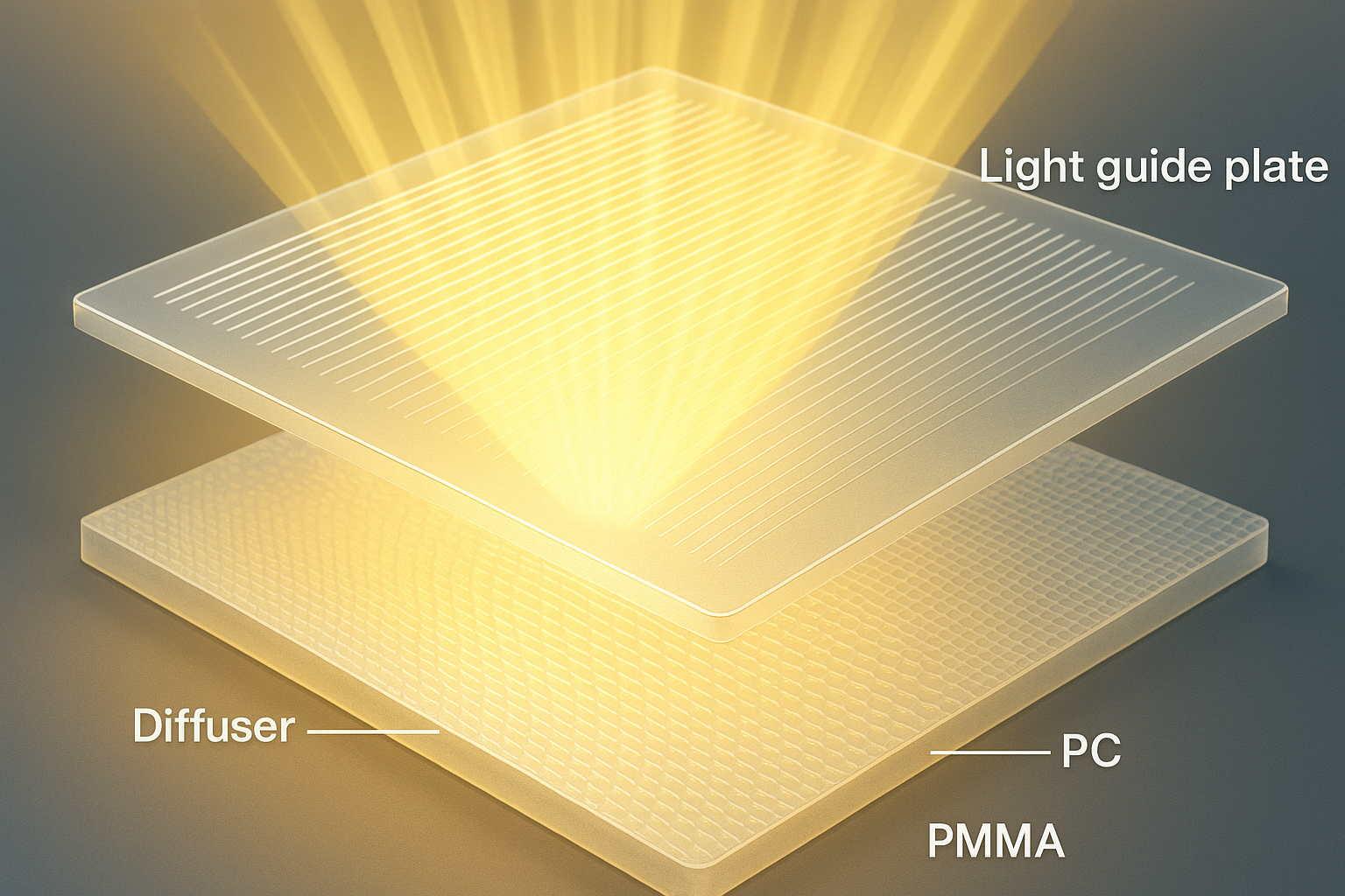
Optical elements shape uniformity and glare. Edge‑lit relies on LGP precision; both architectures depend on diffuser quality.
Materials: PMMA typically offers high clarity with good aging resistance; PC adds impact resistance but may have different yellowing behavior. Ask for supplier datasheets and UV exposure test results.
Microstructures: Laser‑etched or printed patterns redistribute light; quality affects uniformity and efficiency. Request samples or photometry demonstrating uniform luminance.
Microprismatic diffusers help control brightness at high angles, supporting lower glare. Honeycomb or micro‑lens structures can further manage luminance.
Procurement tip: Request diffuser transmittance, haze, and angular distribution data, plus UGR calculations under a defined room model.
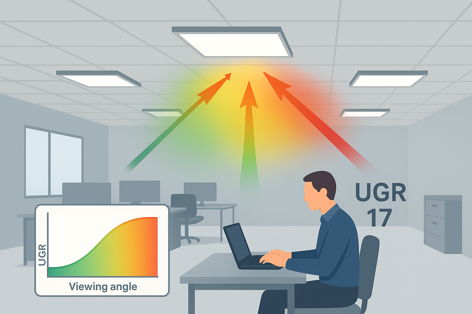
Glare control is a key buying criterion in office and educational projects. The Unified Glare Rating (UGR) is a widely used method to quantify discomfort glare from luminaires.
UGR depends on the luminaire’s luminous intensity distribution, luminous area, observer position, and background luminance. Buyers should request manufacturer photometric data files (IES) and confirm UGR modeled under specified room conditions.
Method context: The CIE technical note on UGR (2023) explains measurement setup and the photometric basis used in calculations.
Practical step: Ask for UGR values reported for typical office rooms and seating positions, and ensure calculations match your local design standard.
Offices/classrooms often target lower glare (commonly cited around UGR < 19 in practice), but verify thresholds against the governing standard in your region.
When comparing suppliers, ensure UGR data is derived from actual photometry, not theoretical claims.
The driver affects power quality, flicker, dimming behavior, and long‑term reliability. A few measurable targets go a long way in procurement.
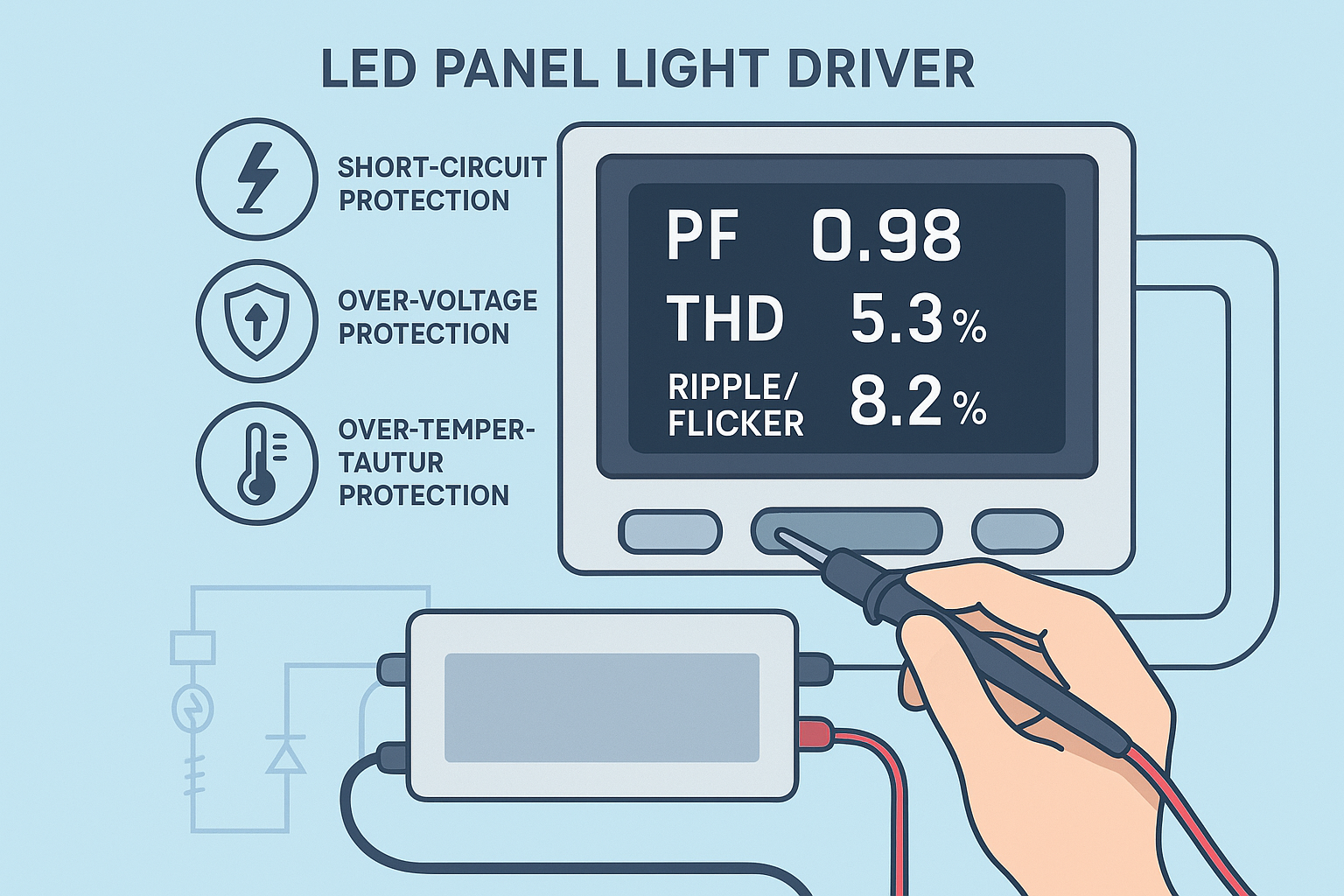
Power factor (PF): For commercial settings, specify PF ≥ 0.90 and confirm in driver datasheets or LM‑79 test results.
Total harmonic distortion (THD): Target ≤ 20% at full output to reduce grid distortion.
Ripple/flicker: Seek low output current ripple and flicker‑free dimming; validate via lab reports or onsite measurement.
Protections: Short‑circuit, over‑voltage, and over‑temperature protections help prevent premature failures.
For measurement context and driver education, see the industry learning resources from PACLights, including guides to measuring drivers and electrical calculations.
Controls: Confirm 0–10V or DALI compatibility as specified; request documentation for dimming curves and flicker performance.
DLC influence: The DLC SSL V6.0 & LUNA V2.0 page outlines controllability fields and QPL mechanics—use it to verify model listings and control capabilities.
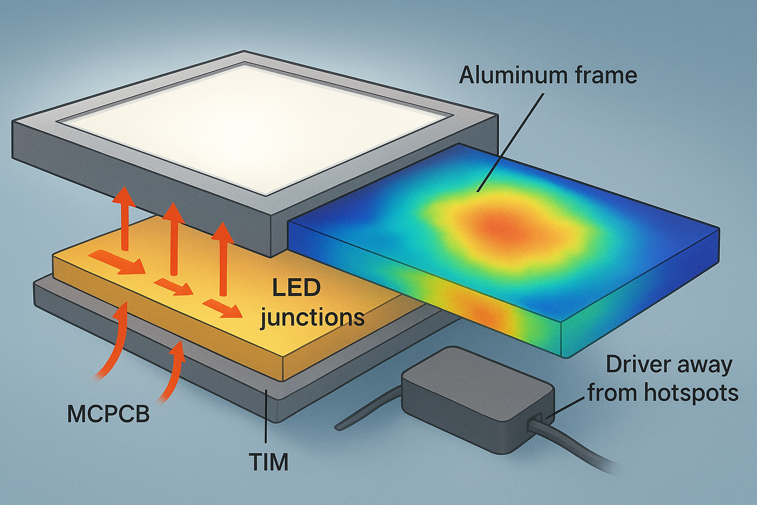
Thermal design underpins lifetime and color stability. In panels, heat must flow from LED junctions through the MCPCB and frame to ambient. Weak links raise temperatures and accelerate degradation.
Think of heat like water: it flows fastest through continuous, wide channels. Your job is to ensure those channels exist.
Continuous conduction: Specify tight mechanical contact between MCPCB and frame, avoid gaps, and use thermal pads or paste where necessary.
Materials: Favor higher thermal conductivity paths—aluminum frames with substantial surface area; consider emissive finishes.
Evidence: Application notes from component makers highlight thermal behavior and measurement—for example, ams OSRAM’s guidance on LED thermal points and processing notes for ceramic LEDs and MCPCBs.
TIMs: Choose pads or pastes with adequate thermal conductivity and compliance; aim for thin bond lines and full coverage.
Driver placement: Keep drivers away from hotspots to avoid thermal stress; ensure airflow or heat‑spreading around the driver compartment.
QA in procurement: Include thermal imaging in acceptance testing, checking for hotspots; review teardown photos to confirm TIM use and assembly alignment.
High‑output arrays: Vendor materials like Lumileds COB brochures describe thermal efficiencies enabling smaller heatsinks—use these documents to set realistic expectations for thermal design.
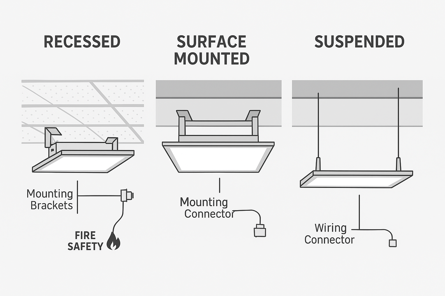
Mounting hardware and wiring kits affect install time and safety. Buyers should plan around ceiling types and maintenance access.
Recessed kits: For grid ceilings, ensure correct dimensions and fire safety considerations.
Surface kits: Confirm bracket strength and attachment methods for solid ceilings.
Suspended kits: Verify cable ratings and length adjustability.
Wiring: Confirm conductor sizes, connectors, and strain reliefs.
For practical installation overviews, see KEOU’s public resource on installation components and methods.
Incorrect dimmer matching causing flicker or driver stress.
Poor cable management creating mechanical strain.
Inadequate ceiling support or misaligned cutouts.
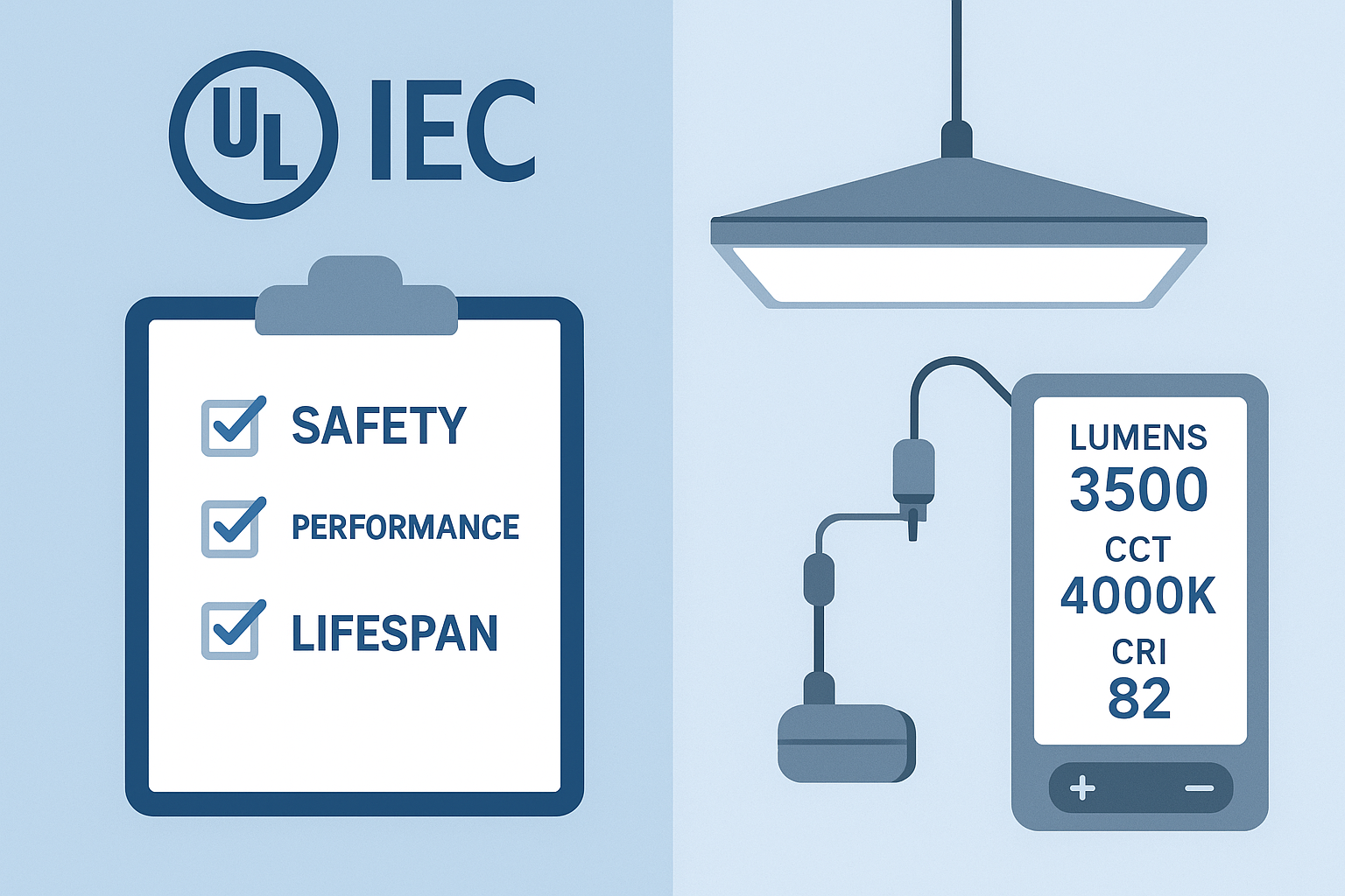
Compliance and independent testing protect projects from safety and performance risks. Decide upfront what documents each SKU must provide.
UL safety: UL 1598 covers luminaires in non‑hazardous locations, including construction and electrical safety. Verify applicable marks and model coverage.
IEC safety: IEC 60598‑1 provides general safety requirements internationally; align with regional adoption.
Photometry: Request an LM‑79 report (lumens, watts, efficacy, CCT/CRI, distributions) from accredited labs; DOE purchasing guidance references LM‑79 for SSL products, as seen in federal procurement materials.
Lifetime: Obtain LM‑80 data for the LED package/module and a TM‑21 projection summary (e.g., L70 at given temps); check IES portals for standards context: IES standards.
DLC listing: Verify the SKU in the QPL under SSL V6.0 & LUNA V2.0 and ensure controllability fields match your spec.
For broader certification reading relevant to North American projects, KEOU’s site has guidance on UL/ETL compatibility contexts.
Certificates: Match model numbers, electrical ratings, and enclosure descriptions; check the issuing body and certification date.
Lab reports: Confirm accreditation, test setup details, and consistency between datasheets and LM‑79/LM‑80 reports.
Photometry files: Ensure IES files correspond to the exact diffuser/optics configuration you’re buying.
A concise checklist you can copy into your RFP or PO notes.
Architecture: Edge‑lit or backlit specified; diffuser type (microprism/honeycomb) noted.
Materials: Aluminum frame alloy/finish; MCPCB copper weight and dielectric thermal conductivity; TIM spec; LGP material (PMMA/PC) if edge‑lit.
Driver: PF ≥ 0.90; THD ≤ 20%; low ripple; protections (SCP/OVP/OTP); dimming protocol (0–10V/DALI) and flicker requirements.
Optics: UGR target under defined room model; request IES files and UGR calculation notes.
Compliance: UL/IEC certificate numbers; LM‑79 photometry; LM‑80 package/module reports; TM‑21 projections; DLC QPL listing link.
Mounting/installation: Kit type (recessed/surface/suspended); wiring connectors; strain relief; maintenance access.
“Provide LED panel light components and documentation as follows: UL 1598/IEC 60598 compliance; LM‑79 photometry from an accredited lab; LM‑80 for LED package/module and TM‑21 L70 projections; DLC SSL V6.0 QPL listing with controllability fields. Driver PF ≥ 0.90, THD ≤ 20%, demonstrably low ripple with flicker‑free dimming on specified protocol (0–10V/DALI). UGR values modeled for a standard office room, validated with IES files and diffuser details. Thermal path continuity documented (MCPCB copper weight, TIM spec), driver placed outside hotspots.”
As you evaluate installation wiring and compatibility in retrofits, see the internal resource on wiring for panel lights.
A: Look for an LGP mention (edge‑lit) versus a direct LED array behind a diffuser (backlit). Exploded diagrams or photometry notes typically reveal this.
A: Specify microprismatic diffusers, request UGR calculations under your room model, and verify with actual IES photometry. Compare values near the workstation viewing angles.
A: LED binning tolerances and diffuser variations can shift appearance. Request tighter binning and diffuser specs, and verify with sample reports.
A: It improves power quality, but you still need to verify ripple/flicker behavior and dimming stability under your controls.
A: Ask for teardown photos, MCPCB and TIM specs, and consider simple infrared imaging during incoming inspection to spot hotspots.


