
Author: Huang Publish Time: 17-08-2026 Origin: Site


Flexible LED tape lighting has transformed modern architectural lighting design. From recessed ceiling coves in commercial office towers to exterior accent lighting across retail complexes, low-voltage LED light strips allow electrical contractors and MEP designers to deliver clean, continuous linear illumination. However, project sites rarely feature wall lengths or cove dimensions that perfectly match factory reel lengths. Installers must frequently trim, join, and wire LED tape in the field to fit bespoke spatial dimensions.
Understanding how cuttable LED strip lights work requires examining their internal electrical architecture. Unlike conventional mains-voltage wiring, a low-voltage DC LED strip is an engineered printed circuit board designed with repeating, independent electrical groups. Trimming a strip outside designated cut lines destroys the internal circuit path and leaves dark segments. Conversely, cutting precisely across copper solder pads maintains electrical continuity and provides robust solder or terminal connection points.
This technical guide analyzes the internal Flexible Printed Circuit (FPC) mechanics of cuttable LED strips, evaluates solderless clip connectors versus soldered joints for commercial reliability, outlines 12V versus 24V voltage drop calculations, and details field-sealing methodologies for IP-rated installations.
To understand why an LED light strip continues to operate after being cut with shears, one must inspect the underlying Flexible Printed Circuit (FPC) trace routing. An LED tape light is not a simple single-loop series circuit. If it were, severing the conductor at any point would break the entire circuit and extinguish every diode on the reel.
Instead, flexible LED strips operate as a repeating chain of independent parallel circuit segments connected across two continuous main power traces—a positive (+) bus and a negative (-) bus—that run the full length of the FPC substrate.
DC Power Bus (+12V / +24V Continuous Trace)
o-------------------+-------------------+-------------------o R Current ResistorR Current ResistorR Current Resistor (LED 1) (LED 1) (LED 1) (LED 2) (LED 2) (LED 2) (LED 3) (LED 3) (LED 3) o---+-------------------+-------------------+---------------o
DC Power Bus (GND / Return Continuous Trace)
As detailed in Waveform Lighting's technical reference on the series-parallel internal schematic of LED strip lights (2026), each independent segment forms a complete, self-contained sub-circuit containing a fixed number of light-emitting diodes in series paired with one or more surface-mount current-limiting resistors.
The main positive and negative copper traces deliver DC supply voltage (typically 12V DC, 24V DC, or 48V DC) simultaneously down the entire length of the tape. Because each diode segment bridges these two main buses in parallel, removing or trimming a segment from the end of the line does not disrupt the supply voltage delivered to the remaining upstream segments.
Within each individual segment, however, the diodes are wired in series:
12V DC Strips: Diode forward voltage typically ranges between 3.0V and 3.3V per LED chip. Wiring 3 LEDs in series creates a cumulative forward voltage drop of approximately 9.0V to 9.9V. The remaining 2.1V to 3.0V is dropped across a surface-mount resistor to regulate forward current to approximately 20 mA.
24V DC Strips: Wiring 6 LEDs in series creates a forward voltage drop of approximately 18.0V to 19.8V, leaving the remaining voltage for the current-limiting resistor. Because 24V architecture requires half the operating current of a 12V strip for the same overall wattage, it drastically reduces thermal dissipation and line losses.
COB (Chip-on-Board) Strips: COB tape replaces individual SMD plastic packages with hundreds of microscopic flip-chips mounted directly onto the FPC beneath a continuous phosphor silicone matrix. Despite the seamless line of light, COB strips utilize tightly packed parallel circuit groups with micro-cut intervals spaced every 10 mm to 25 mm.
LED chips are current-driven semiconductor devices with low internal resistance once their forward voltage threshold is exceeded. Supplying DC voltage directly to an unregulated series chain of LEDs causes thermal runaway—as the junction temperature rises, internal resistance drops, drawing exponential current until the chips overheat and fail.
Surface-mount device (SMD) resistors placed within each cut segment enforce strict current control. The resistor value (R) is calculated via Ohm's Law:
R = (V source - V forward) / I target
For example, on a 24V strip with 6 LEDs in series (V forward = 19.2V) targeting a current of 20 mA (0.02A):
R = (24V - 19.2V) / 0.02A = 240 Ω
This resistor absorbs minor voltage fluctuations from the power driver and prevents overcurrent degradation across the entire segment.
Every commercial LED light strip features clearly defined cutting zones along its length, denoted by printed scissor icons, dashed cut lines, or exposed copper pads.
Key Takeaway: A cut mark designates the exact boundary where one independent parallel circuit segment ends and the next begins. Trimming precisely at this line preserves the electrical integrity of both sections.
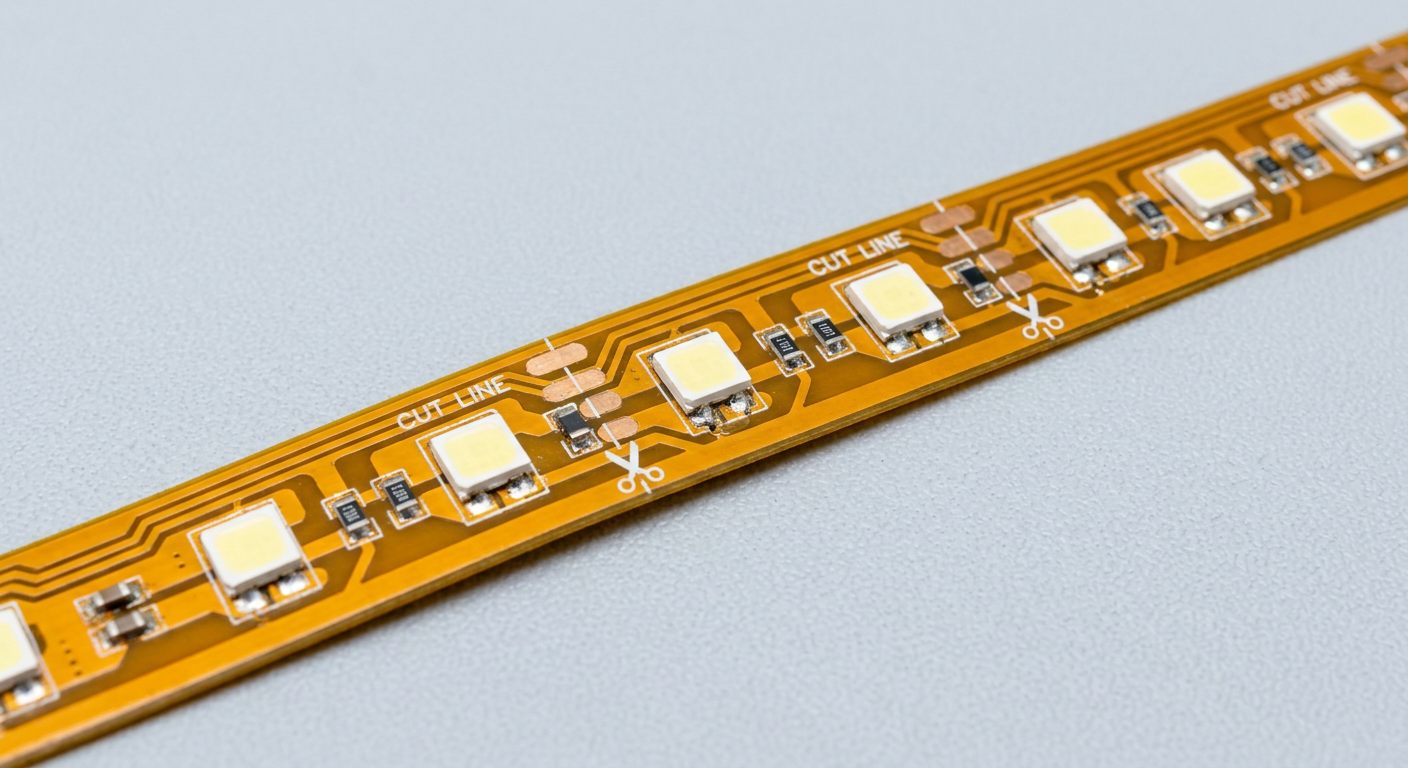
At each designated cut mark, the manufacturer widens the internal positive and negative copper traces into twin, oval-shaped copper solder pads. The printed cut line bisects these copper pads directly down the center.
When an installer makes a straight cut through the middle of the pad:
The cut cleanly separates the parallel electrical segment on the left from the segment on the right.
Half of the copper pad remains attached to the upstream segment, while the other half remains attached to the downstream segment.
The remaining copper half-pads expose clean, uninsulated metallic contacts suitable for soldering lead wires or clamping solderless clip connectors.
Segment A Segment B
[LED] [LED] [LED] [Resistor] [LED] [LED] [LED] [Resistor]
---- Trace ---- Copper Pad | Copper Pad ---- Trace ---- <-- Cut Line Bisects Pad → ---- Trace ---- Copper Pad | Copper Pad ---- Trace ----
If a technician cuts an LED strip away from the marked copper pad—for example, clipping the FPC directly between two LEDs within a segment—the series connection inside that specific segment is severed.
Because the series circuit loop is broken:
Current cannot flow through the current-limiting resistor or the remaining diodes in that segment.
All 3 LEDs (on a 12V strip) or 6 LEDs (on a 24V strip) within that trimmed group go dark immediately.
The rest of the strip upstream continues to illuminate normally because its parallel connection to the main power bus remains intact.
The downstream cut section becomes completely unpowered until new lead wires are soldered to the nearest valid copper pad set.
As highlighted in SYA Lighting's engineering breakdown of copper solder pads and cut mark alignment (2026), precision cutting is critical in high-density installations to avoid wasted tape stock and unsightly dark spots in architectural coves.
The mechanical and electrical durability of a cuttable LED strip depends heavily on the copper weight of its Flexible Printed Circuit:
1oz Copper (35 µm Thickness): Common in entry-level commercial products. The thin copper layer offers higher electrical resistance, resulting in elevated heat generation, lower current-carrying capacity, and delicate solder pads that easily delaminate if exposed to excessive iron heat.
2oz Heavy Copper (70 µm Thickness): According to Flex Plus FPC's analysis of 2oz heavy copper flexible circuit boards (FPC) (2026), doubling the copper weight to 70 µm doubles the conductor cross-section. This reduces line resistance by 50%, allows traces to carry up to 4.8 A safely at modest temperature rises, enhances heat dissipation through aluminum profile channels, and provides thermal durability during field soldering.
Leading manufacturers like KEOU Lighting's 13-year semiconductor and LED manufacturing facilities utilize dual-layer 2oz rolled-annealed copper FPC substrates across their commercial-grade indoor LED light strips and drivers to ensure superior current distribution and mechanical pad strength.
Once an LED tape light is cut to length, technicians must re-establish electrical connections—either to attach DC lead wires from the power driver, bridge corners, or join cut segments end-to-end. Two primary connection methodologies dominate commercial field installation: solderless clip connectors and direct wire soldering.
Evaluation Metric |
Solderless Clip / IPC Connectors |
Direct Wire Soldering |
|---|---|---|
Connection Type |
Mechanical spring-pressure or Insulation Piercing Contacts (IPC). |
Metallurgical bond using lead-free rosin-core solder. |
Contact Resistance |
Moderate to High (0.05 Ω to 0.20 Ω per junction). |
Extremely Low (< 0.005 Ω per joint). |
Current Rating Limit |
Typically capped at 3 A to 5 A maximum. |
Full FPC trace rating (up to 8 A+ on 2oz copper). |
Vibration Resistance |
Susceptible to micro-flicker under HVAC vibration or physical movement. |
Impervious to mechanical vibration or thermal expansion fatigue. |
Profile & Housing Fit |
Bulky plastic housing; may not fit narrow 8 mm or 10 mm aluminum extrusions. |
Ultra-low profile; seamless fit inside any aluminum lens profile. |
Labor Efficiency |
High speed; no specialized soldering equipment or hot-work permits required. |
Requires skilled technicians, soldering irons, flux, and heat-shrink tools. |
Ideal Application |
Indoor accent lighting, short display runs, quick site adjustments. |
High-bay coves, continuous commercial runs, exterior IP67 installations. |
Solderless connectors utilize plastic snap-lock housings containing tiny brass contact prongs. When closed over a cut FPC end, the prongs press firmly onto the exposed copper pads (gap-type connectors) or pierce through the wire insulation (IPC connectors) to bridge electrical contact without heat.
While solderless connectors reduce on-site labor hours, MEP engineers must account for their technical limitations:
Pad Alignment: The strip must be cut perfectly perpendicular. Jagged or diagonal cuts cause contact misalignment, shorting adjacent pins on multi-channel RGBW or Tunable White strips.
Current Limitations: Contact prongs rely on localized mechanical pressure. Passing high current (> 4 A) through a spring-clip contact causes localized heating, spring fatigue, contact oxidation, and eventual flickering or joint failure.
Physical Constraints: Solderless clip housings add 3 mm to 5 mm of width and height to the tape. In slim architectural aluminum channels, the clip housing often blocks the plastic diffuser lens from snapping shut cleanly.
Direct soldering forms a permanent, fused chemical bond between the stranded copper lead wire and the FPC pad. For high-end commercial projects, continuous architectural coves, and hidden ceiling runs, direct soldering remains the gold standard for electrical reliability.
RH Strip Lighting's field evaluation of soldering versus solderless terminal connectors (2026) highlights best practices for field-soldering cut LED tape:
Pad Preparation: Clean the exposed copper pad with isopropyl alcohol (IPA) to remove residual silicone, oils, or oxidation.
Tinning the Contacts: Apply a small amount of rosin flux to the copper pad. Touch a temperature-controlled iron (320°C to 350°C) to the pad for 1 to 2 seconds and melt a small dome of lead-free solder onto the pad. Pre-tin the stripped wire end similarly.
Joining: Place the tinned wire onto the tinned pad, apply the iron tip for 1 second until the solder flows together seamlessly, and remove heat while holding the wire stationary for 2 seconds to form a shiny, solid solder joint.
Insulation: Slide a piece of dual-wall adhesive-lined polyolefin heat-shrink tubing over the joint to provide strain relief and environmental sealing.
⚠️ Warning: Never hold a soldering iron on an FPC pad for longer than 3 seconds. Prolonged high heat melts the underlying polyimide adhesive layer, causing the copper pad to delaminate and tear away from the circuit board permanently.
A frequent challenge in commercial linear lighting is voltage drop—the gradual decline in DC voltage along the length of the conductor due to trace resistance. When installing long continuous tape runs, voltage drop causes visible dimming, uneven illumination, and color temperature shifts (toward red/warm spectrums) at the far end of the installation.
The voltage drop (ΔV) across a two-conductor DC circuit is calculated using the formula:
ΔV = I × (2 × L × ρ / A)
Where:
I = Total operating current in amperes (A).
L = Length of the run in meters (m).
ρ = Electrical resistivity of copper (1.68 × 10⁻⁸ Ω·m).
A = Cross-sectional area of the copper trace in square meters (m²).
According to Future House Store's engineering guide on voltage drop calculations and max run lengths (2026), commercial installations must maintain total voltage drop below 3% to 5% of the nominal supply voltage (< 0.36V drop for 12V systems; < 0.72V drop for 24V systems).
Because total wattage (P) equals voltage (V) multiplied by current (I), doubling the operating voltage from 12V to 24V cuts the required operating current in half for the same total lumen output:
I₁₂V = 120W / 12V = 10A vs. I₂₄V = 120W / 24V = 5A
Because line losses increase with the square of the current (P loss = I⊃2; × R), 24V systems experience 75% lower power dissipation losses along the FPC copper traces than 12V systems.
Consequently, maximum recommended continuous single-ended feed lengths are:
12V DC LED Strips: Maximum single feed of 5 meters (16.4 ft). Beyond 5 m, far-end dimming becomes visually apparent.
24V DC LED Strips: Maximum single feed of 10 meters (32.8 ft).
48V DC Constant-Current Strips: Maximum single feed of 20 to 30 meters (65.6 to 98.4 ft), utilizing integrated linear IC driver chips inside each segment to maintain uniform current regardless of line resistance.

When architectural designs require uninterrupted linear runs exceeding maximum single-ended feed limits—such as a 30-meter perimeter hotel lobby cove—contractors must implement power injection topologies rather than connecting strips end-to-end in a single series line.
Dual-Ended Feeding: Running DC power leads to both the start and end of a 10m to 15m strip section. This effectively halves the distance current must travel through the FPC copper traces, keeping voltage within target limits.
Parallel Trunk Bus (Home-Run Distribution): Installing a heavy-gauge main DC feeder cable (e.g., 14 AWG or 16 AWG stranded copper wire) alongside the aluminum profile. Tap connections branch off the main trunk cable every 5m or 10m to feed short, independent LED tape segments in parallel. This approach prevents cumulative current from passing through the delicate FPC copper pads.

When commercial LED tape is installed in high-humidity indoor environments, commercial kitchens, or outdoor architectural building facades, maintaining its Ingress Protection (IP) rating after field cutting is vital to prevent environmental failure.
IP Rating |
Construction Format |
Field-Cutting & Resealing Methodology |
|---|---|---|
IP20 |
Open-frame dry FPC board with surface SMD chips. |
Standard scissor cut at copper pad; no environmental sealing required. |
IP65 |
Surface nano-coating or PU/Silicone drop-glue. |
Cut through silicone layer. Scrape 3 mm of silicone off pads; solder wires; apply neutral RTV silicone conformal coating. |
IP67 / IP68 |
Full silicone hollow/solid extruded sleeve enclosure. |
Cut hollow tube; trim internal tape 5 mm shorter; solder leads; inject neutral RTV silastic glue; slide on IP end cap; shrink. |
When field-cutting waterproof IP65 or IP67 LED tape:
Exposing Pads: Carefully trim away 3 mm to 5 mm of the top silicone jacket surrounding the cut copper pad using a precision hobby knife, taking care not to nick or score the underlying copper trace.
Soldering Leads: Clean the exposed copper with isopropyl alcohol and solder stranded lead wires directly to the pads.
Applying Conformal Neutral Glue: Apply high-grade, non-corrosive neutral-cure silicone sealant (RTV silastic) over the solder joint and exposed FPC edges. Avoid acidic acetic-cure silicones, which emit vinegar fumes during curing that oxidize copper traces and degrade LED phosphor layers.
End-Cap Crimping: Slide a color-matched silicone end cap over the glued joint and secure it with dual-wall adhesive heat-shrink tubing to create an airtight, moisture-impermeable seal.
For complete specs on matching architectural linear fixtures with architectural LED panel lights for office coves and commercial LED downlights, review the complete KEOU commercial LED lighting catalog.
No. LED light strips must only be cut directly across the designated copper pads marked with a scissor icon or dotted line. Cutting outside these designated zones breaks the internal series circuit within that segment, causing that entire 3-LED or 6-LED group to stop functioning.
If you cut between cut marks, the specific diode group surrounding the cut will go dark because its series circuit loop is broken. However, the rest of the strip upstream remains fully functional. To fix the mistake, simply trim off the damaged partial segment back to the nearest valid copper pad set and make a clean connection there.
Yes. Direct wire soldering forms a permanent metallurgical bond with extremely low electrical resistance (< 0.005 Ω), high current carrying capacity, and complete immunity to HVAC vibrations or thermal expansion fatigue. Solderless clips are useful for quick adjustments or temporary setups, but soldering is strongly recommended for permanent commercial installations.
This is caused by voltage drop. As DC current travels down long, thin copper FPC traces, electrical resistance reduces the voltage reaching the far end. To fix this, upgrade to a 24V system, shorten individual feed runs, or install a dual-ended power injection wiring topology.
For commercial lighting distributors, electrical wholesalers, and engineering contractors, sourcing high-reliability LED tape and linear fixtures is essential for reducing site labor and avoiding warranty callbacks.
Backed by 13 years of semiconductor packaging and LED fixture manufacturing experience, KEOU Lighting provides full-spectrum OEM and ODM customization services for global commercial markets:
Heavy 2oz/3oz Copper FPC Boards: Engineered with double-sided rolled copper for minimal voltage drop, superior heat dissipation, and robust solder pad pull strength.
Precision Binning & High CRI: SDCM < 3 color consistency across all COB and SMD LED strip series (> 90 CRI / R9 > 50).
Custom Reel Lengths & Pre-Pigtail Assembly: Factory-cut to precise project schedule lengths with IP67 pre-molded IP-rated pigtail connectors to eliminate on-site soldering labor.
Comprehensive Global Compliance: Certified to CE, RoHS, CB, and Middle East regional standards for commercial, hospitality, and residential projects.
Explore customized linear lighting, LED drivers, and architectural fixtures by visiting KEOU Lighting's official commercial portal or contacting our engineering team for project quotes and sample kits.


